Thursday, January 31, 2008

Process of DVD Recording

Process of DVD Recording

Burn DVD


Menu: Project - Burn DVD from disk

This is the last step in the DVD creation process.

With our DVD Project having been Compiled, there are a set of files that DVD-lab has prepared for you in the Output folder as set in the Compile process. At this point, the DVD Author has choices as to how to convert this set of files into a DVD master disc. You can either use the DVD-lab built-in recording module or you can choose to use a third party DVD recording software such as Nero, Prassi, Gear, etc...

It is common that you are supplied with a DVD recording software that was bundled with your DVD-R/DVD+R burner. This software may be better optimized for your particular drive. The DVD-lab built-in DVD recording module is a general ASPI writing application and should work fine. In an ideal world, either one would work equally well.

DVD-lab Disc record window

The DVD-lab Disc record window is automatically detached. That means it runs as a separate process independent from DVD-lab, you could even close DVD-lab and the recording will continue.


Here are some of the parameter choices for the DVD-lab Disc record window.

Input Folder
The Input Folder is the same as the Output folder in Compile. That means this is the folder where the VIDEO_TS and AUDIO_TS folders are expected to be.


Device
The DVD recording drive you want to write to, presented as the O/S recognizes it.

Media Type
Set if you want to burn DVD Video or a Mini-DVD.


Mini-DVD is a DVD format burned on the CD-R. Obviously you can put far less data on a CD-R (about 700 MB) than on DVD (4.3 GB)

The size indicator on the bottom can help you to determine how much data you can record to the disc. You have to keep your data below the red area.

Note: While you will be able to play the CD-R on a computer not all standalone players will be able to play the Mini-DVD. In fact such format is not officially supported. The reason is that CD's have far less density of data so in order to play the large DVD video bitrate they have to spin much faster than DVD. Not all DVD drives in players are ready for this so the functionality to DVD files from CD-R is often simply disabled. However a number of Asian or re-branded Asian US models of players use a standard PC type of DVD drive which allows for fast spin of CD.

DVD-RW/DVD+RW Tools
For those using a re-writable media, the DVD-RW needs to be formatted if they were already used - click the Erase/Format button to do this. The more common DVD-R media do not need any formatting.


The DVD-RW and +RW needs to be finalized after writing. This takes quite a large amount of time on RW media. Please be patient until this important process is completed.

Options:

Test Write checkbox

Use this option by checking the Test Write checkbox to have DVD-lab do a trial run at writing a DVD. This option does not write anything to disk or your hard drive, it merely goes through the motions to insure that all of the content and menus within the DVD project are correctly prepared and defined.

Create Image checkbox

You can choose to have DVD-lab create a large file on your hard drive which is an the image of a DVD disc instead of burning. The result will be one big IMG file. That IMG file can be used with a number of third party DVD recording software to replicate a DVD disc from this image file, as many times as you like, whenever you like. Some software will look for a ISO file name extension, if so, just rename the file to a .ISO extension. This method has the advantage of speed as the DVD image is all prepared on your hard drive, it is then a just matter of how fast your DVD burner drive will burn that image.

Hybrid DVD Writing button

You can add additional files and folders to the DVD master disc with the Hybrid DVD Writing option. What this option will do is setup an alternate filesystem on the DVD master disc which is called an ISO filesystem. The ISO format is what a standard CD uses while the DVD video is in UDF/ISO. This is perfectly DVD "legal" as the DVD player doesn't know or care about this ISO filesystem's contents, it just looks for a UDF filesystem.

It doesn't matter at all what the content or nature of these files are. They are just files, not Windows or Mac or Linux files, just files. As they are recorded into the ISO file system domain, they are available on any computer with a DVD drive. This offers the DVD-lab Author some creative options for bonus content that would be available to a computer user on any O/S that supports a DVD drive.

For example, you can create an autorun project in Multimedia Builder and record it to DVD as an extra feature when used on PC. HTML based content may be placed here as well, be sure to indicate to your computer users where to find your HTML starting page (ex: index.html).

Note: The space used by the Hybrid DVD Writing option counts in the entire Project space value. You only get so much space on a DVD (4.7G), this option uses part of that. Do the math to be sure you have room for this extra area.

Write button

As expected, click this button to start the DVD writing (burn) process.
Note: It is not recommended to do any work on the computer during DVD writing. Things like reading/writing to hard-drive may easily ruin your DVD-R. Try to let the burning process be the only thing your computer is running until it is completed.

Tuesday, January 29, 2008

Installing DVD drive

Installing a DVD Drive

This guide was developed to instruct users on the proper method to install an ATA based optical drive into a desktop computer system. These instructions are valid for any form of optical based drive such as CD-ROM, CD-RW, DVD-Rom or DVD burners. It is a step-by-step instruction guide with photographs detailing the individual steps.
The very first thing to do whenever working on a computer system is to make sure there is no power. Shut down the computer if it is running. Once the computer has safely shut down, turn the internal power off by slipping the switch on the back of the power supply and removing the AC power cord.


2. Opening up the Computer

At this point, the computer needs to be opened up to properly install the CD or DVD drive into the computer. The method for opening the case will vary depending upone the case. Most new systems will use a panel or door on the side of the system while older systems may require the whole cover be removed. Remove and set aside and screws fastening the cover or panel to the computer case and then remove the cover.

3.Remove the Drive Slot Cover

Computer cases can generally hold a number of external drives but only a few are generally used. Any unsed drive slot has a cover that prevents dust from entering the computer and makes the case look better. To install the drive, it will be necessary to remove a 5.25" drive slot cover from the case. Removal of these generally is done by pushing some tabs either on the inside or outside of the case. Some may be screwed into the case.

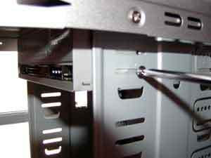
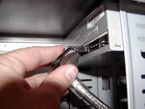
4. Setting the IDE Drive Mode

The majority of all CD and DVD drives for computer systems use the IDE interface. This interface can have two devices on a single cable. Each device on the cable must be placed into the appropriate mode for the cable. One drive is listed as the master and the other secondary drive is listed as a slave. This setting is generally handled by one or more jumpers on the back of the drive. Consult the documentation or diagrams on the drive for the location and settings for the drive.


If the CD/DVD drive is going to be installed on an existing cable, the drive needs to be set into the Slave mode. If the drive is going to reside on its own IDE cable alone, the drive should be set to the Master mode.

5. Placing the CD/DVD Drive into the Case

At this point, the CD/DVD drive needs to be placed into the computer. The method for installing the drive will vary depending on the case. The two most common methods for installing a drive into a case is either through drive rails or directly into the drive cage.

Rails: Place the drive rails onto the side of the drive and fasten it with screws. Once the drive rails have been placed on both sides of the drive, slide the drive and rails into the appropriate slot in the case. Make sure to affix the drive rails so that the drive is flush with the case when it is fully inserted into the case.

Drive Cage: Slide the drive into the slot in the case so that the drive bezel is flush with the computer case. When this is done, fasten the drive to the computer case by placing screws into the appropriate slots or holes in the case.


6. Attaching the Internal Audio Cable

Many people use the CD/DVD drive inside of their computer to listen to audio CDs. In order for this to work, the audio signal from the CD needs to be routed from the drive to the computer audio solution. This is typically handled by a small two wire cable with a standard connector. Plug this cable into the back of the CD/DVD drive. The other end of the cable will plug either into a PC audio card or motherboard depending upon which the computer uses for audio. Plug the cable into the connector labeled as CD Audio.


7. Attaching the Drive Cable to the CD/DVD

At this point, the CD/DVD drive needs to be attached to the computer through an IDE cable. For most users, the drive will reside as a secondary drive to the hard drive. If this is the case, locate the free connector on the IDE ribbon cable between the computer and the hard drive and plug it into the drive. If the drive is going to be on its own cable, plug the IDE cable into the motherboard and one of the other connectors of the cable into the CD/DVD drive.


8. Plug the Power to the CD/DVD

The only internal item left to do for installing the drive is to plug it into the power supply. This is done by locating one of the 4-pin Molex connectors from the power supply and inserting it into the power connector on the CD/DVD drive.

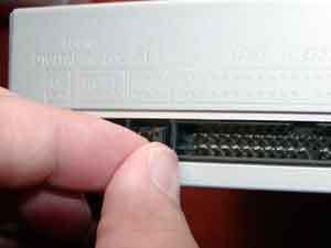
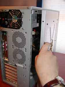
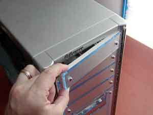
9. Closing up the Computer Case

At this point the drive is fully installed into the computer case so it can be closed up. Replace the panel or cover to the computer case. Be sure to fasten the cover or panel back to the case using the screws that were set aside when the cover was removed.


10. Powering up the Computer

All of the installation steps for the CD or DVD drive are now completed. The only thing left to do is return power to the computer. Plug the AC cord back into the power supply and be sure to flip the switch to the on position.

The computer system should automatically detect and begin using the new drive. Since CD and DVD drives are very standardized, it should not be necessary to install any specific drivers. Be sure to consult the instruction manual that came with the drive for any specific instructions for your operating system.

Thursday, January 17, 2008

CPU Sockets


CPU Sockets


In the beginning, a CPU socket was compatible with just one kind of processor. This story changed with the launching of the 486 processor and the massive use of ZIF (Zero Insertion Force) socket, also known as LIF (Low Insertion Force), which has a lever that installs and removes the CPU from the socket without the need of the user or the technician to press the CPU down in order to be installed on the socket. The use of this socket lowered a lot the chances of breaking or bending the CPU pins during its installation or removal. The use of the same pinout by more than one processor allowed the user or the technician to install different processor models on the same motherboard by just removing the old CPU and installing the new one. Of course the motherboard needed to be compatible with the new CPU being installed and also properly configured.

Since then both Intel and AMD have been developing a series of sockets and slots to be used by their CPUs.

The socket created to be used together with the very first 486 processor wasn’t ZIF and didn’t allow you to replace the CPU with a different processor model. Even though this socket didn’t have an official name, let’s call it socket 0. After socket 0 Intel released socket 1, which had the same pinout of socket 0 with the addition of a key pin. It also adopted ZIF standard, allowing the installation of several different processor types on the same socket (i.e. on the same motherboard). Other socket standards were released for the 486 family after socket 1 – socket 2, socket 3 and socket 6 – in order to increase the number of CPU models that could be installed on the CPU socket. Thus socket 2 accepts the same CPUs accepted by socket 1 plus some more models, and so on. Even though socket 6 was designed, it was never used. Thus we usually call the pinout used by 486-class processors as “socket 3”. Intel called “overdrive” the possibility of a socket to accept more than one CPU model. Intel also adopted this name on CPUs that used a pinout from an older CPU, in order to allow it to be installed on an older motherboard.

The first Pentium processors (60 MHz and 66 MHz) used a pinout standard called socket 4, which was fed with 5 V. Pentium processors from 75 MHz on were fed with 3.3 V and thus required a new socket, called socket 5, which was incompatible with socket 4 (a Pentium-60 couldn’t be installed on socket 5 and a Pentium-100 couldn’t be installed on socket 4, for example). Socket 7 uses the same pinout as socket 5 with the addition of one key pin, accepting the same processors accepted by socket 5 plus new CPUs, especially CPUs designed by competing companies (the real difference between socket 5 and socket 7 is that while socket 5 always fed the CPU with 3.3 V, socket 7 allowed the CPU to be fed with a different voltage level, like 3.5 V or 2.8 V, for example). Super 7 socket is a socket 7 capable of running up to 100 MHz, used by AMD CPUs. We usually call the Pentium Classic and compatible CPUs pinout as “socket 7”.

As you may notice, sockets and pinouts at this stage were very confusing, as a given processor could be installed on different socket types. A 486DX-33 could be installed on sockets 0, 1, 2, 3 and, if it were released, 6.

For the next CPUs manufacturers followed a simpler scheme, where each CPU could be installed only on just one socket type.

2nd Trinal Assignment # 2: Package Types

Intel CPU Processor Identification (http://support.intel.com/support/processors/procid)


There are several package types for Intel® processors. These different package types are illustrated below along with a brief explanation of how to easily identify them.


FC-PGA Package Type


The FC-PGA package is short for flip chip pin grid array, which have pins that are inserted into a socket. These chips are turned upside down so that the die or the part of the processor that makes up the computer chip is exposed on the top of the processor. By having the die exposed allows the thermal solution can be applied directly to the die, which allows for more efficient cooling of the chip. To enhance the performance of the package by decoupling the power and ground signals, FC-PGA processors have discrete capacitors and resistors on the bottom of the processor, in the capacitor placement area (center of processor). The pins on the bottom of the chip are staggered. In addition, the pins are arranged in a way that the processor can only be inserted one way into the socket. The FC-PGA package is used in Pentium® III and Intel® Celeron® processors, which use 370 pins.


Pentium III and Intel® Celeron® processor


OOI Package Type


OOI is short for OLGA. OLGA stands for Organic Land Grid Array. The OLGA chips also use a flip chip design, where the processor is attached to the substrate face-down for better signal integrity, more efficient heat removal and lower inductance. The OOI then has an Integrated Heat Spreader (IHS) that helps heatsink dissipation to a properly attached fan heatsink. The OOI is used by the Pentium 4 processor, which has 423 pins.


FC-PGA2 Package Type

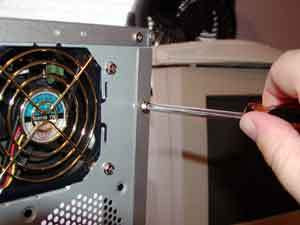
FC-PGA2 packages are similar to the FC-PGA package type, except these processors also have an Integrated Heat Sink (IHS). The integrated heat sink is attached directly to the die of the processor during manufacturing. Since the IHS makes a good thermal contact with the die and it offers a larger surface area for better heat dissipation, it can significantly increase thermal conductivity. The FC-PGA2 package is used in Pentium III and Intel Celeron processor (370 pins) and the Pentium 4 processor (478 pins).


PGA Package Type


PGA is short for Pin Grid Array, and these processors have pins that are inserted into a socket. To improve thermal conductivity, the PGA uses a nickel plated copper heat slug on top of the processor. The pins on the bottom of the chip are staggered. In addition, the pins are arranged in a way that the processor can only be inserted one way into the socket. The PGA package is used by the Intel Xeon™ processor, which has 603 pins.


PPGA Package Type


PPGA is short for Plastic Pin Grid Array, and these processors have pins that are inserted into a socket. To improve thermal conductivity, the PPGA uses a nickel plated copper heat slug on top of the processor. The pins on the bottom of the chip are staggered. In addition, the pins are arranged in a way that the processor can only be inserted one way into the socket. The PPGA package is used by early Intel Celeron processors, which have 370 pins.


S.E.C.C. Package Type


S.E.C.C. is short for Single Edge Contact Cartridge. To connect to the motherboard, the processor is inserted into a slot. Instead of having pins, it uses goldfinger contacts, which the processor uses to carry its signals back and forth. The S.E.C.C. is covered with a metal shell that covers the top of the entire cartridge assembly. The back of the cartridge is a thermal plate that acts as a heatsink. Inside the S.E.C.C., most processors have a printed circuit board called the substrate that links together the processor, the L2 cache and the bus termination circuits. The S.E.C.C. package was used in the Intel Pentium II processors, which have 242 contacts and the Pentium® II Xeon™ and Pentium III Xeon processors, which have 330 contacts.


S.E.C.C.2 Package Type


The S.E.C.C.2 package is similar to the S.E.C.C. package except the S.E.C.C.2 uses less casing and does not include the thermal plate. The S.E.C.C.2 package was used in some later versions of the Pentium II processor and Pentium III processor (242 contacts).


S.E.P. Package Type


S.E.P. is short for Single Edge Processor. The S.E.P. package is similar to a S.E.C.C. or S.E.C.C.2 package but it has no covering. In addition, the substrate (circuit board) is visible from the bottom side. The S.E.P. package was used by early Intel Celeron processors, which have 242 contacts.


Laptops:


Micro-FCPGA


The micro-FCPGA (Flip Chip Plastic Grid Array) package consists of a die placed face-down on an organic substrate. An epoxy material surrounds the die, forming a smooth, relatively clear fillet. The package uses 478 pins, which are 2.03 mm long and .32 mm in diameter. While there are several micro-FCPGA socket designs available, all of them are designed to allow zero-insertion force removal and insertion of the processor. Different from micro-PGA, the micro-FCPGA does not have an interposer and it includes capacitors on the bottom side.


Micro-FCBGA


Micro-FCBGA (Flip Chip Ball Grid Array) package for surface mount boards consists of a die placed face-down on an organic substrate. An epoxy material surrounds the die, forming a smooth, relatively clear fillet. Instead of using pins, the packages use small balls, which acts as contacts for the processor. The advantage of using balls instead of pins is that there are no leads that bend. The package uses 479 balls, which are .78 mm in diameter. Different from Micro-PGA, the micro-FCPGA includes capacitors on the top side.


Micro-BGA2 Package


The BGA2 package consists of a die placed face-down on an organic substrate. An epoxy material surrounds the die, forming a smooth, relatively clear fillet. Instead of using pins, the packages use small balls, which acts as contacts for the processor. The advantage of using balls instead of pins is that there are no leads that bend. The Pentium® III processor uses the BGA2 package, which contains 495 balls.


Micro-PGA2 Package


The micro-PGA2 consists of a BGA package mounted to an interposer with small pins. The pins are 1.25 mm long and 0.30 mm in diameter. While there are several micro-PGA2 socket designs available, all of them are designed to allow zero-insertion force removal and insertion of the mobile Pentium III processor.


MMC-2 Package


The Mobile Module Cartridge 2 (MMC-2) package has a mobile Pentium® III processor and the host bridge system controller (consisting of the processor bus controller, memory controller and PCI bus controller) on a small circuit. It connects to the system via a 400-pin connector. On the MMC-2 package, the thermal transfer plate (TTP) provides heat dissipation from the processor and host bridge system controller.


Other Package Types


CPGA (Ceramic Pin Grid Array)


CPGA stands for Ceramic Pin Grid Array, a type of connection for CPUs where the processor's die is attached to a heat-conducting ceramic plate which is pierced by an array of pins which make the requisite connections to the socket.


Popular CPUs that employ CPGA are the "classic" Socket A Athlon and the Duron, both from AMD.


OPGA (Organic Pin Grid Array )


The Organic Pin Grid Array (OPGA) is a type of connection for integrated circuits, and especially CPUs, where the silicon die is attached to a plate out of an organic plastic which is pierced by an array of pins which make the requisite connections to the socket.


A popular type of CPU to employ the OPGA is the AMD Athlon XP.


2nd Trinal Assignment # 1: Motherboard Form Factors

Definition of: Baby AT motherboard A smaller version of the original AT motherboard used in the IBM PC/AT. Introduced in 1987, the Baby AT reduced width from 12" to 8.5". Although its maximum length was 13", most boards were only 9" or 10" long. The Baby AT was the first PC motherboard to build in sockets for I/O ports (serial, parallel, etc.), which were cabled to connectors on the back of the case. Widely used in 386, 486 and early Pentium PCs, the Baby AT was superseded by the ATX motherboard.


Definition of: AT motherboard A motherboard that follows the same design and 12x13" form factor that was in the original IBM PC/AT. It was superseded by the Baby AT.


Definition of: ATX motherboard (Advanced Technology EXtended motherboard) The PC motherboard that superseded the Baby AT design. The ATX layout rotated the CPU and memory 90 degrees, allowing full-length expansions to be plugged into all sockets. The power supply blows air over the CPU rather than pulling air through the chassis.Introduced in 1995, the ATX was the first PC motherboard to not only include I/O support (serial, parallel, mouse, etc.), but to place all the connectors directly on the motherboard. Prior to the ATX, only the keyboard connector was attached to the motherboard.Numerous variations of the ATX were subsequently introduced with both smaller and larger form factors, including the microATX, Mini ATX, FlexATX and Extended ATX (see PC motherboards).


Definition of: LPX motherboard (Low-Profile EXtended motherboard) A low-profile PC motherboard for slimline cases, introduced in 1997 by Western Digital. Unlike boards for desktop and tower cases that hold the expansion cards perpendicular to the board, cards plug into a riser card on the LPX and are parallel with the board. Having a 9" width, the Mini LPX version decreased the length from 13" to 11". See PC motherboards.


Definition of: NLX motherboard (New Low-Profile EXtended motherboard) A low-profile PC motherboard from Intel for slimline cases, introduced in 1987. Unlike boards for desktop and tower cases that hold the expansion cards perpendicular to the board, cards plug into a riser card on the NLX and are parallel with the board. See PC motherboards.

Wednesday, November 28, 2007

Assignment # 2: Installing Windows 2000

How To Install Windows 2000 Professional

On This Page
SUMMARY
Installing Windows 2000 Professional


SUMMARY
This article describes how to install Windows 2000 Professional.

Installing Windows 2000 Professional

To install Windows 2000 Professional, follow these steps:
1. Start the installation by using one of the following methods:

•Start from the Windows 2000 Professional installation CD-ROM. Make sure that the CD-ROM is set to start before the hard disk starts. Insert the CD-ROM, and then when you are prompted, press any key to start the Windows 2000 Professional Setup program.

•Start from boot disks. Insert Disk 1, and then insert each of the remaining three floppy disks when you are prompted to do so.For additional information about creating boot disks for Windows 2000, click the article number below to view the article in the Microsoft Knowledge Base:
197063 (http://support.microsoft.com/kb/197063/EN-US/) How to Create Setup Boot Disks for Windows 2000

•Start from within a current operating system. Insert the CD-ROM, and then, at a command prompt, type drive:\i386\winnt32.exe and then press ENTER, or if this is an installation on a computer that has no previous installation of Windows, type drive:\i386\winnt.exe and then press ENTER, where drive is the letter of the CD-ROM drive.

2.Setup inspects your computer's hardware configuration and then begins to install the Setup and driver files. When the Microsoft Windows 2000 Professional screen appears, press ENTER to set up Windows 2000 Professional.

3.Read the license agreement, and then press the F8 key to accept the terms of the license agreement and continue the installation.

4.
When the Windows 2000 Professional Setup screen appears, either press ENTER to set up Windows 2000 Professional on the selected partition, or press C to create a partition in the unpartitioned space.

5.If you choose to install Windows 2000 Professional on a file allocation table (FAT) partition, specify whether you want to:

•Leave the current file system intact.
•Format the partition as FAT16.
•Convert the existing file system to the NTFS file system.

Format the partition by using the NTFS file system.Press ENTER after you make your selection. Setup examines the existing hard disks and then copies the files that are needed to complete the installation of Windows 2000 Professional. After the files are copied, the computer restarts.Important Do not press a key to boot from your CD-ROM drive when your computer restarts.

6.When the Windows 2000 GUI Mode Setup Wizard appears, click Next to start the wizard. Setup detects and installs such devices as a specialized mouse or keyboard.

7.When the Regional Options dialog box appears, customize your installation of Windows 2000 Professional for locale, number format, currency, time, date, and language, if necessary. Click Next.

8.In the Personalize Your Software dialog box, type your name and the name of your organization, and then click Next.

9.In the Product ID dialog box, type the 25-character product key, and then click Next.

10.In the Computer Name and Password dialog box, either accept the default name that Setup generates or assign a different name for the computer. When you are prompted for an administrative password, type a password for the Administrator account. (You can leave the box blank; however, this is not recommended.) Click Next.

11.In the Date and Time Settings dialog box, set the correct date and time for your computer. You can also specify which time zone you are in and set the computer to automatically adjust the clock for daylight saving time. Click Next.

12.Setup installs the networking software and detects your network settings. When the Network Settings dialog box appears, click either

•Typical to set default network settings such as File and Print Sharing for Microsoft Networks, Client for Microsoft Networks, and TCP/IP protocol that uses Dynamic Host Configuration Protocol (DHCP), or
•Custom to specify the network components that you require for your network environment,and then click Next.

13.In the Workgroup or Computer Domain dialog box, specify the workgroup or the domain to join. If you indicate that you are part of a domain, specify your domain user name and password. Click Next.Setup installs the networking components.

14.During the final stage of installation, Setup installs Start menu items, registers components, saves settings, and removes temporary files. When the Completing the Windows 2000 Setup Wizard dialog box prompts you to do so, remove the Windows 2000 CD-ROM, and then click Finish to restart the computer.

15.After the computer restarts, click Next in the Welcome to the Network Identification Wizard dialog box.

16.In the Users of This Computer dialog box, specify either that users must enter a user name and password or that you want Windows 2000 to automatically log on a specific user when the computer starts. Click Finish.When the Windows 2000 Professional desktop appears, the installation is complete.

Tuesday, November 27, 2007

Assignment # 2: Installing Windows 98

How to install Windows 98

NOTE: This article is for informational use only. It does not contain any troubleshooting information. If you are searching for troubleshooting information that is not mentioned in this article, search the Microsoft Knowledge Base again

On This Page
SUMMARY
MORE INFORMATION
Before Purchasing Windows 98
Before Installing Windows 98
Installing Windows 98
Common Windows 98 Setup Issues
Highlights for Windows Web Site

SUMMARY
loadTOCNode(1, 'summary');
This article provides general information about installing Windows 98. This information can help you avoid problems that might arise during the installation process and help make the installation process as smooth as possible.

MORE INFORMATION
loadTOCNode(1, 'moreinformation');

Before Purchasing Windows 98

Before you purchase Windows 98, make sure that your computer meets the minimum hardware requirements for running Windows 98. The minimum hardware requirements include:

•486DX 66 megahertz (MHz) or faster processor (Pentium recommended)
•16 megabytes (MBs) of memory (24 MB recommended)
•120 MB of free hard disk space (typical installation requires approximately 195 MB of free hard disk space, but the required space may vary from 120 MB to 295 MB, depending on your computer's configuration and the options that you choose to install)
•CD-ROM or DVD-ROM drive
•3.5-inch high-density floppy disk drive
•Video adapter and monitor that support video graphics adapter (VGA) or higher resolution
•Microsoft Mouse or compatible pointing device

Although Windows 98 includes more than 1,200 new drivers, not all third-party manufacturers' hardware drivers are compatible with Windows 98. Some older computers or devices may require an updated basic input/output system (BIOS) or device driver to fully support Windows 98.

You can use the Windows 98 Upgrade version to upgrade Microsoft Windows version 3.1x, Microsoft Windows for Workgroups version 3.1x, or Microsoft Windows 95 or later to Windows 98. If Windows 3.1x, Windows for Workgroups 3.1x, or Windows 95 is not currently installed, you can use the Windows 98 Upgrade Setup program to install Windows 98 if you can provide the disks or CD-ROM from an earlier version of Windows to confirm your eligibility for the upgrade. Because the Windows 98 Upgrade version does not include a Startup disk, you must be able to start from the computer's hard disk to install the Windows 98 Upgrade.

To install the non-upgrade version of Windows 98, you do not need an earlier version of Windows or MS-DOS. Because the non-upgrade version of Windows 98 includes a Startup disk, you do not need to be able to start from the computer's hard disk.

Before Installing Windows 98

Before you upgrade your existing version of Windows to Windows 98, perform the following steps:

•Read the Setup.txt file in the Win98 folder on the Windows 98 CD-ROM, and perform any additional preinstallation steps as suggested.

•Make sure that your computer is not infected with a virus. To do so, run an antivirus program that has the latest virus signatures and allow the program to remove any viruses that it finds.
•Disable any programs that run automatically, including antivirus programs, screen savers, and system utilities. After Setup is finished, you can re-enable these programs.
•Uninstall any utilities or tools that protect or encrypt the master boot record (MBR) or partition table (for example, uninstall the Bootlock utility that is included with Symantec Norton Your Eyes Only). Make sure that you check with the software manufacturer before you reinstall the program to make sure that the version that you want to install is compatible with Windows 98.
•Back up all critical data on your hard disk. Although it is unlikely that you will encounter a serious problem when you install Windows 98, it is always a good idea to perform a complete system backup before you install a new operating system. When you upgrade your computer's operating system, an error might occur (such as a problem that is the result of incompatible hardware or a power failure) that could temporarily or permanently prevent you from gaining access to the data on your hard disk.

Installing Windows 98

If you want to install Windows 98 on a computer that does not have an installed operating system, go to http://support.microsoft.com/kb/221829/EN-US/

If you are upgrading Windows 95, start Windows 95, and then insert the Windows 98 CD-ROM. Follow the instructions on your screen to install Windows 98.

If you are not upgrading Windows 95, see the appropriate section of the Windows 98 Setup.txt file for specific installation instructions.